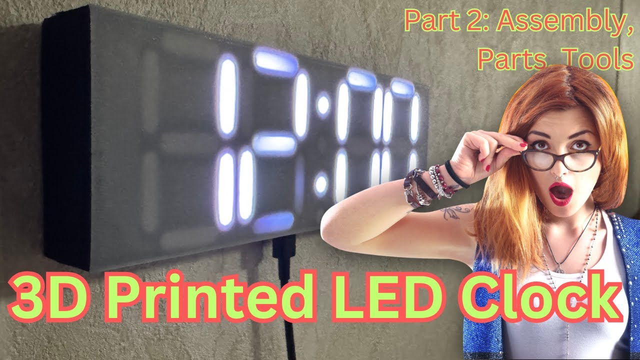
🔌 Ready to wire up your 3D printed clock? In this second part of our four-part series, we’ll cover all the electronics components and wiring setup needed for your smart LED clock.
⏱️ Timeline:
0:00 – Print Quality Check
0:13 – Model Clean-up Tips
0:43 – Parts Overview
1:44 – Resistor Selection
2:32 – LED Strip Introduction
4:24 – LED Strip Preparation
5:53 – Wiring Components
8:00 – Connection Details
10:16 – Assembly Preview
10:34 – Complete Parts List
12:05 – Tools & Materials Review
13:19 – Wiring Diagram Explanation
14:14 – Physical Layout Planning
🔧 What We’ll Cover:
– Print quality assessment
– LED strip preparation and cutting
– Component selection and verification
– Wiring diagram walkthrough
– Connection methods and options
– Testing setup recommendations
🛠️ Required Tools:
– Soldering Iron
– Wire Strippers
– 3D Printing Snips
– Small Screwdriver Set
– Heat Shrink Tubing
📦 Required Parts:
– ESP8266/ESP32 D1 Mini: [[Amazon Link](https://amzn.to/4iHuXWk)]
– WS2812B LED Strip (100 LED/m):
– 5V Power Supply (1-2A):
– Micro USB Cable:
– Dupont Wires/Connectors:
– 220 Ohm Resistor:
– M3 Screws (1cm length):
– Breadboard (optional):
📺 Watch the Complete Series:
Part 1: 3D Printing – [https://youtu.be/DS_muPDX8p8]
Part 2: Parts, Tools, and Wiring – [https://youtu.be/uiOuWeXdryE]
Part 3: Final Assembly (Coming Soon)
Part 4: Firmware Setup (Coming Soon)
👉 Quick Version:
Watch the 2.5-minute short: [Coming Soon]
❤️ Like and Subscribe for more DIY smart home projects!
source
